High-Speed Stimuli Generator for Engine Ignition systems

Abstract

WireFlow helped SEM (Svenska Elektromagneter) to develop an advanced, high performance and highly configurable Stimuli Generator (STIG) for up to 12 cylinder ignition systems. The system was built using National Instruments cRIO hardware and LabVIEW/LabVIEW-RT and LabVIEW-FPGA.  The system can define stimulus for each cylinder in terms of ignition pulses, trigger pulses as well as engine speed and analog simulation data – everything relative to the start of an engine cycle (Crank Angle Degrees – CAD). The width of any digital pulse can be set in 0.01 CAD or in 0.1 ms steps resolution. Engine speed can be varied between 0-20 000 RPM, either as a predefined speed profile or manually when the system is running. 

Challenges

SEM is one of the world’s leading producers of electronic ignition systems and engine control systems. SEM develops and produces high-end ignition systems for a variety of engines, ranging from one cylinder engines for chainsaw motors to big gas engine systems with 8 cylinders or more. 

During development, it is important to be able to exactly control all parts of the ignition, like spark position and duration for each cylinder for a number engine cycles – representing a specific startup behavior or mimicking a faulty behavior. 

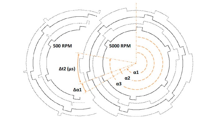
One of the tricky parts is that spark duration can be given in CAD (0.01 degree resolution) or given as a fixed time (0.1 ms) depending on engine type, whereas spark position is always given as a position (CAD) in the engine cycle. In the figure to the left, a fixed configuration for four DO channels are shown for two different engine speeds.

The solid pulse trace is a signal with all data given in CAD in the engine cycle, and the dashed trace displays a situation where the pulse width is given in s. To find the end of a pulse the system has to handle both pure CAD positions (α1+ α1), as well CAD position with time delays (α1+ t2) simultaneously. Because of possible speed changes, the system has to continuously recalculate the end of all pulses where the width is given in s. Because the pulse position and width might not be fixed, the system must also constantly validate that two pulses is not overlapping (e.g. if speed is high enough). The engine speed must also be settable at a specific CAD (in 0.01 steps) with an RPM resolution of 0.01. 

Solution

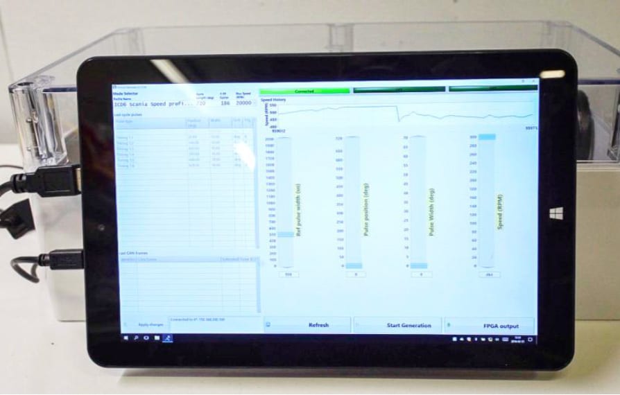
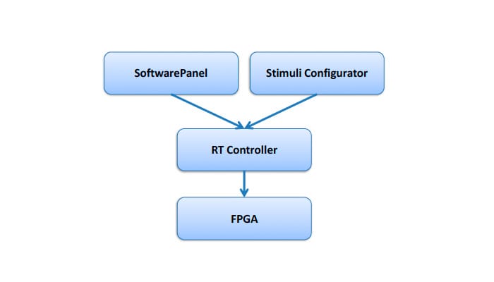
Using LabVIEW and a high end cRIO from National Instruments™ WireFlow created a system that allows the technicians at SEM to select predefined engine cycles using a touch-screen. The user can also manually control all aspects of the ignition cycle, including position and duration of each ignition pulse as well as the reference pulse using different slider bars in the GUI. It is also possible to manually change the RPM value while maintaining the pulse characteristics, i.e. the position and duration regardless if it is given in time- or CAD-domain.  The system consists of four main LabVIEW components, 
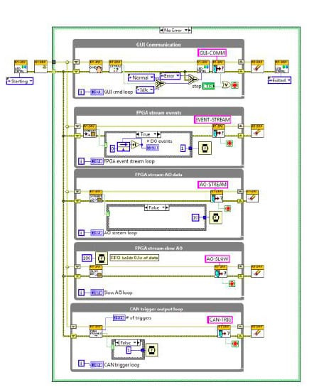
  • The FPGA 
  • The RT Controller 
  • The Runtime control GUI (pictured above) 
  • The Stimuli Configurator GUI 

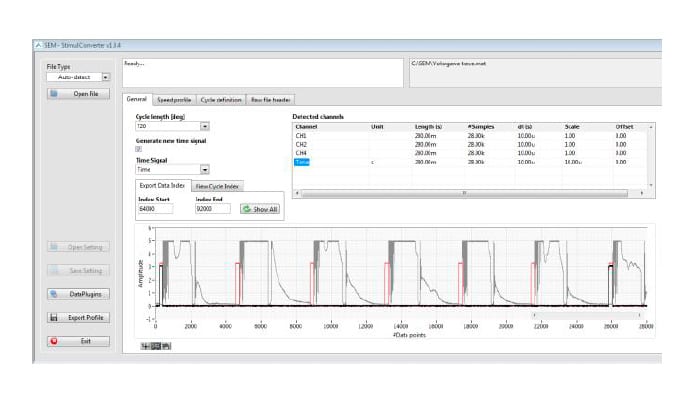
In the offline Stimuli Configurator, GUI technicians define a specific engine cycle with a unique speed profile. The profile is transferred to the cRIO as a TDMS file and played back using the Runtime Control GUI. 

The main focus of the RT controller is to continuously stream the events that define the pulses, speed etc. to the FPGA, and to stream all analog and CAN data that can be triggered by the pulses and which are defined in the Stimuli Creator GUI and stored in the TDMS file.  It also handles all commands sent from the GUI, e.g. pulse characteristics and speed. It also sends status to the GUI, to inform the user about the current speed and the current cycle.  The cRIO-FPGA is the heart of the system and does all the heavy lifting, generating up to 31 channels of digital pulses, where each channel contains up to 13 pulses per engine cycle. It also handles the analog data that the RT process streams to the FPGA at a maximum rate of 192MB/s all triggered from the defined DO pulses. To be able to meet the requirements for both digital and analog I/O, all data has to be calculated in a Single Cycle Timed Loop (SCTL). Outputs can then be generated with the required output accuracy of 0.1s for digital pulses, and better than 0.01 CAD resolution for angle domain data. Running the system at full load, i.e. 20 000 RPM with 31 channels with pulse trains and maximum analog data stream, still only uses ~35% of the cRIO CPU.  In addition to be used during development the system can also be used to playback customer recorded data or to validate scenarios recorded on the lab. Because different customers use different types of instrument to record the data WireFlow developed a versatile tool that can import many different data format (e.g. Yokogawa *.mat files) and convert the data to the Stimuli Generator TDMS format. The tool extracts speed, reference pulses as well as timing and analog data and STIG can then reproduce the recorded data on the test bench. 
Subscribe To Our Newsletter

Subscribe To Our Newsletter

Join our mailing list to receive the latest news and updates from our team.

You have Successfully Subscribed!