Production tester for Battery Management Systems
Taking advantage of WireFlow’s modular test framework
Abstract
A developer and manufacturer of industrial battery products was fortunate enough to close a deal with a company who wanted to buy large quantities of one of their products. This was of course great news, but there were some hefty challenges to deal with, the biggest of which was a very aggressive time plan.
This study describes how WireFlow could help a client by taking full responsibility for design, development and launch of a complete production test setup.
The Challenge
When the deal between our client and their customer was signed, the product was not yet fully developed and there were lots of things that needed to be done in a very short time, such as to complete the products design, industrialize it, set up manufacturing etc. etc.
There was simply no time for our client to fix everything by themselves, and they realized that they needed to partner up with someone who could share the workload.
So, they asked us at WireFlow if we could help them by taking the responsibility to set up a production test process for them.
The task would include:
- Assess the test needs through a circuitry analysis
- Ensure product testability
- Write test specifications
- Design and develop test hardware
- Design and develop test software
- Define a production flow
- Launch the test process at the manufacturing site abroad
We accepted the task and formed a team to meet our client’s needs.
The product
The product in question is the BMS-unit for a battery pack. BMS stands for “Battery Management System” and is an electrical control unit (or ECU) that supervises the charging and load balancing of a battery pack. The battery pack itself is not a part of the tested system, only the BMS. The main components are three CPU’s running the software that optimizes the use of the battery pack.
The production test scope
The purpose with a production test is to ensure that the manufacturing of each sample has been carried out correctly. This includes to check that:
- All components have been mounted correctly, i.e. are not missing or mounted in the wrong direction, and that they are of the right type
- There are no unwanted short-circuits
- All solderings are faultless
This is typically done by manipulating signals at strategic points in the circuit and measure expected, resulting values at other.
A production test is not intended to verify the design of the product, i.e. that the product behaves as described by the requirements. That has been verified in an earlier test instance.
The Solution
From the moment WireFlow was involved, we worked in close relation with the client´s developers and project leaders to ensure that we were in the loop and could follow any turns and tweaks in the development of the product. This was vital due to the to the tight time plan and the agile nature of the product development.
Test needs & Testability
One of the first actions from WireFlow´s side, was to establish what testing should be done at the production line. We also needed to ensure that those tests could indeed be executed, i.e. that that all relevant signals could be accessed and controlled from the test system.
The output of this work was:
- A test specification
- Some re-design of the product hardware for testability
- Development of special test firmware to run on the
CPUs in the DUT during some of the tests - A perception of the requirements of the test platform
WireFlows Framework
One of the reasons that WireFlow felt confident enough to take on this project was that, over time, we have accumulated in-house software, hardware and knowledge which combined constitutes a sort of design pattern for test systems.
Fundamental components of this toolbox are:
- Hardware components
Ex: Relay boards, Power supplies, Sensor simulation modules, Battery management modules. - Software modules
Ex: Hardware drivers, Communication software, TestStand templates - Support systems
Ex: Cloud based test result database, Data exchange & monitoring over internet, label scanner support. - Test fixture
The one used in this project, complemented with a generic, re-usable test hardware setup. More details about this further down. - Document templates
Ex: Design specs, test reports, Project documents. - Workflows
Together with our many years of experience, these components form a versatile platform that enables us to jump-start a project and to move forward at a high pace. Moreover, they have proven themselves in several projects before, which significantly reduces the risk of those pesky bugs and unexpected behaviors late in a project.
These resources were critical for us to be able to deliver a system that met with our client’s requirements on time.
With the test specification and the framework as inputs, we created a production test system for our client.
The mechanics
A vital part of the WireFlow test-system framework is the fixture that we have selected. It is a solution from Ingun and is depicted in Figure 2.
The Ingun fixture is modular and separates the test instrumentation located in the box (or “I/O-box”) at the bottom, from the DUT mounted in the so-called cassette at the top, just under the hood with the blue handle. The two parts are interconnected via a standard high-density connector. The whole fixture and the interior of the I/O-box is all part of WireFlows framework. The only thing specifically developed for the client is the cassette, i.e. the board that mechanically attaches the DUT to the fixture and electrically connects it to the I/O-connector. Everything else is to be considered ready-made, or rather, ready-designed.
If later, our client wishes to introduce another DUT, whose test specification is compatible with the test instrumentation in the I/O-box, they only need to design a new cassette. Signal pin-out is defined in software.
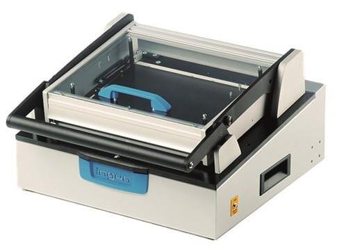
Figure 1. Fixture box
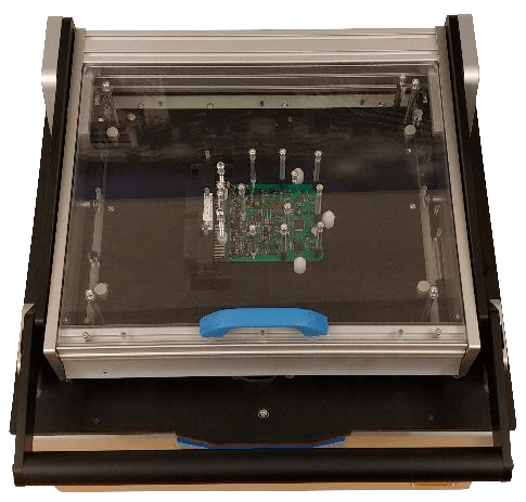
Figure 2.
Test object mounted in the cassette
The test hardware
The I/O-box contains the following instrumentation:
Manipulation of digital signals and measuring analog signals
This is handled by a multifunction data acquisition board from National Instruments controlled via USB.
CAN communication (2 channels)
Handled by two USB-CAN interface devices, also from National Instruments.
JTAG programming
To program the three CPUs residing in the product there are three separate USB devices for parallel software loading.
Programmable power supplies
3 programmable power supplies for independent sourcing and simulation on DUT interfaces. Controlled via USB.
Solid state relays
There are several high and low current solid-state relays. These are WireFlow’s own design and part of our framework.
Signal conditioning boards
WireFlows own design and part of our framework.
USB-hub
To connect all the USB-instruments inside the box.
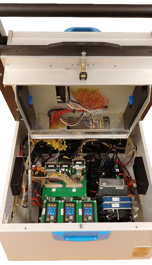
Figure 3.
Instrumentation in the fixture-box
This setup, mounted in the I/O-box, is a generic design, owned by WireFlow, and is an off-the-shelf product.
It has been designed and dimensioned to have the ability to test most circuit-boards unless there any extraordinary properties like, for example physical dimensions, extreme currents etc.
The box allows for customization, so if a product has an interface not included in the standard setup, it can be complemented with support for, for example:
- USB
- Ethernet
- Wireless
- Etc
In Figure 3 you can see the interior of the I/O-box with all test hardware mounted. On the bottom of the opened lid you can see the underside of the cassette.
The software
Just like with the hardware, modularity is important when it comes to the software involved in the production tester. Some software is part of the platform and some is custom made for this particular client. Below is a list of the main software components:
System API (LabVIEW) Offers a programming interface towards the instruments in the fixture. For those instruments that belongs to the platform, the code is part of the platform. There is also some client-specific code that has been developed. Those are implemented as separate modules but are accessed in the same way as the platform modules.
Test cases (TestStand) Each test case is implemented as a test-sequence in TestStand. They utilize the System API to access the test system resources.
Test sequences (TestStand) The complete test cycle for a DUT is implemented as a sequence of test case sequences.
Operator interface (LabVIEW) The operator interface is a very stripped-down GUI that leads the operator through the short test procedure which includes scanning a label, insert the DUT, run the test sequence and observe the result. It is generic and also a component of the test framework.
The support systems
Label scanner
The platform has built in support for a hand scanner. It can be used for, for example, registering serial numbers for the DUTs.
Label printer
Support for print out of a label to put on DUT after test.
Test Data Management (SkyWATS)
SkyWATS is a test data management system sold by Virinco. It has features like:
- Test result storage
- Data analysis
- Reporting
- Any-where access through a web-client
- Programming API for both LabVIEW and TestStand (and other languages as well)
WireFlow has been using SkyWATS for a long time and use it by default in our platform.
The controller
The controller is a standard Windows PC whose main purpose is to run the test sequences. It is connected to the fixture with a single USB-cable and to the production site’s network via ethernet.
In addition to test execution, it also handles:
- Data base communication
- Label scans
- Label prints
It is a rather low-spec all-in-one PC, i.e. computer built into a 15” display, with touch screen. running Windows 10.
Summary
Our client made a deal with a customer who was in a hurry and turned to WireFlow for help to set up a production test site. Thanks to our framework, we could meet with their requirements and time plans and be their one-stop-shop for the production test site that they needed.
Figure 4 below shows the whole setup delivered to our client at their manufacturing site.
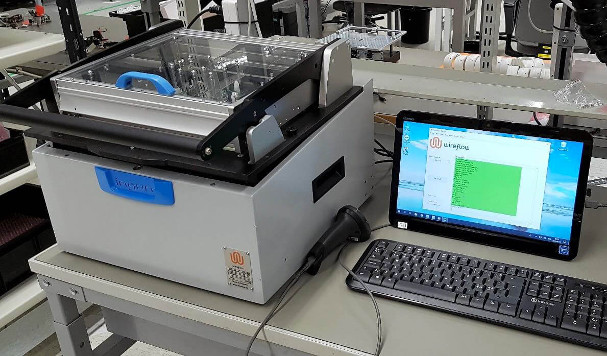
Figure 4. Complete production tester setup with fixture to the left, hand scanner in the middle and the controller PC to the right.