Charge and Test System for Li-Ion Battery
A production system designed for Toyota Material Handling
The Challenge
Toyota Material Handling Manufacturing Sweden is one of the world’s largest factories for manufacturing of warehouse trucks.
Toyota was in progress of introducing a new generation of Li-Ion batteries for their trucks and needed new charging and test stations for the battery manufacturing line.
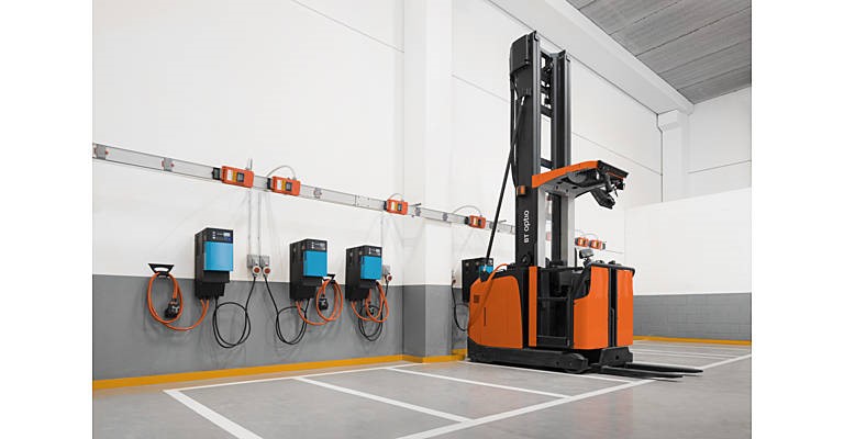
Figure 1. A forklift with Li-Ion batteries is being charged
The Solution
WireFlow designed a charging and test cabinet containing two types of battery chargers and the electrical control and measurement functions needed to charge and test the battery types manufactured by Toyota.
A NI 9147 Ethernet RIO Expansion Chassis was chosen as the platform to control the electrical devices and to collect voltage and current measurements. An external PC is used to interact with the operators and to execute the charging end test procedure. The software was developed with LabVIEW NXG.
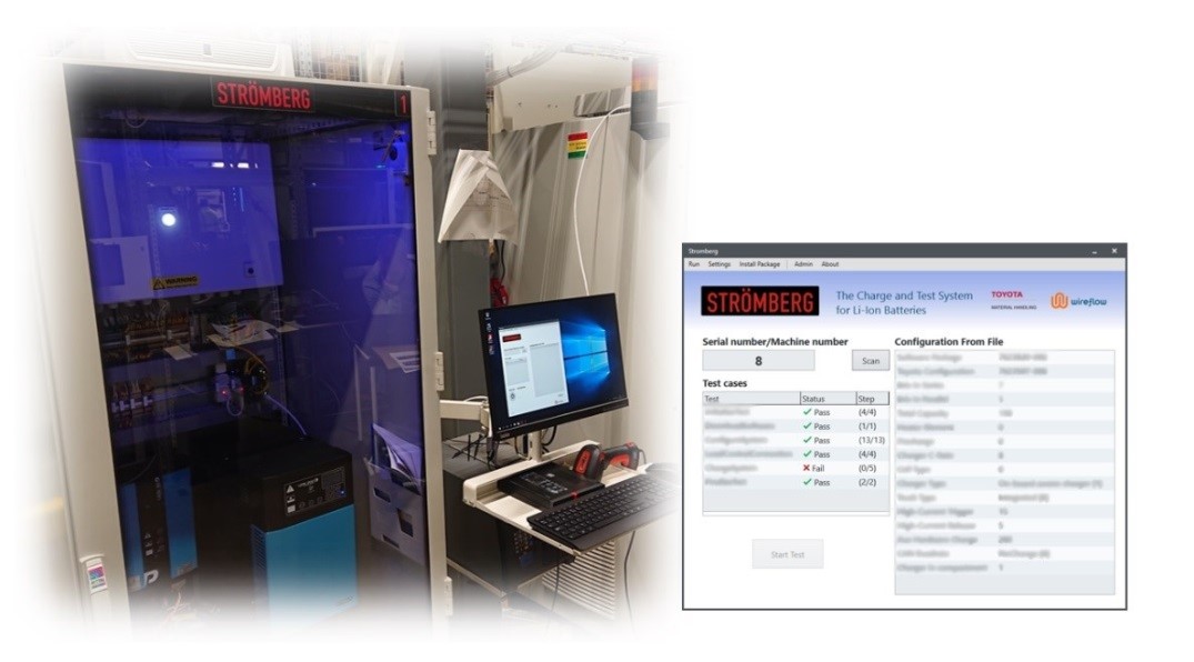
Figure 2. Cabinet, PC and Operator control panel
The Cabinet
The cabinet is powered by a 3-phase mains voltage input. All mains voltage circuits are located within a separate box inside the cabinet for extra safety. Functions to handle emergency stop and door open detection are located in this mains electrical circuit.
Two high power battery chargers are installed in the cabinet. Which charger to use depends on the type of battery currently being connected to the cabinet.
An NI 9147 Ethernet RIO Expansion chassis with I/O modules is used to control the chargers and select which of the two chargers that shall be used.
The cabinet communicates with the batteries via CAN communication, so inside the cabinet there is a CAN communication interface connected to the same Ethernet network as the RIO Expansion chassis. This means that the external PC can connect to both the RIO expansion chassis and to the battery being tested using a single Ethernet cable.
There is a high-power resistor in the cabinet that is used for load tests on the batteries. During a load test the system measures voltage and current from the battery to check if it has the expected characteristics.
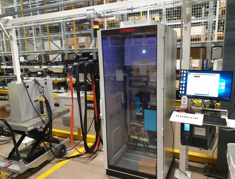
Figure 3. A battery being charged and tested by the cabinet.
The software
The software application is executing on a PC located next to the cabinet. When a new battery is connected to the charging and test system, the operator uses a hand-scanner to input the model and serial numbers of the battery into the software application. From the battery model number, the application can decide the battery’s topology, regarding the number of cells connected in parallel and serial. It can also select the correct and latest battery firmware, battery parameter configuration and appropriate test limits for the following tests.
The first step is to download the firmware into the onboard computer of the battery. This programming is done over CAN bus to the battery.

Figure 4. The operator initiates the charging and test sequence.
After programming and configuration of the onboard computer, the system will perform a load test on the battery. This is done by connecting a power resistor to the battery and measure voltage and current, hereby characterizing the battery behavior. The system will also communicate with the onboard computer in the battery to check that all individual cell voltages and temperatures are within the specified limits.
The final step is to charge the battery to the correct charging level that it shall have when mounted into the truck. The system will during this charging also continuously monitor the individual cell voltages and temperatures to make sure that there are no abnormalities.
A challenge during the software development was to implement the CAN communication with the onboard computer in the battery during the charging and test procedure. The PC software must emulate a truck’s CAN traffic in order to make the onboard computer believe it is actually located inside a truck. Failing to do this properly will trigger safety functions inside the battery, preventing it from going into charging mode.
Besides the software running on the PC there is also a small software application running on the NI RIO expansion chassis inside the cabinet. This software was developed in LabVIEW FPGA and acts as an interface between the PC application and the measurement modules in the NI RIO expansion chassis.
The software in the PC was developed using the new LabVIEW NXG. This made it easy to create a functional and modern looking user interface for the PC. Besides communicating with the NI RIO expansion chassis and the CAN interface in the cabinet the PC software also interacts with the truck manufacturing data base to get configuration information about the batteries being manufactured. During the tests, extensive logs are also continuously being saved to disc.
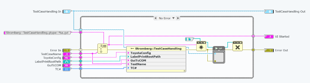
Figure 5. Part of the source code developed with LabVIEW NXG