ECU Prototype Test System for Thermal Power Control
cRIO HIL-solution for software and hardware testing at Azelio
Abstract
This study describes a project that WireFlow executed for Azelio.
Azelio is working on new ways to store renewable energy, so it can be made available when it is most needed. They combine the well-known Stirling engine, with an innovative Thermal Energy Storage using the phase changing characteristics of a metal alloy, to recover the energy during the dark hours. During the development they needed a flexible testbed for RnD and validation.
The system was built in LabVIEW and used standard I/O as well as custom electronics to realize the customer requirements.
Keywords: LabVIEW, Python, CompactRIO, EtherCAT, ThermoCouple
The Challenge
The challenge with a prototype test system is just that – it will be testing prototypes. This means that requirements and I/O probably will change during development. Another challenge is how to access the I/O on the CompactRIO platform from the Python test environment Azelio uses.
The requested test system was originally required to support ~60 I/O channels, including a number of thermocouple simulators (both Type-K and Type-R) as well as different industrial communication buses like CAN and Modbus. It also had to be able to simulate a number of loads to create a realistic environment to the Device Under Test (DUT)
During the project the scope changed to include ~120 I/O channels, with new signal types such as PT100 simulations.
Since the prototypes might change in the future the system must also be easy to upgrade without too much work.
The Solution
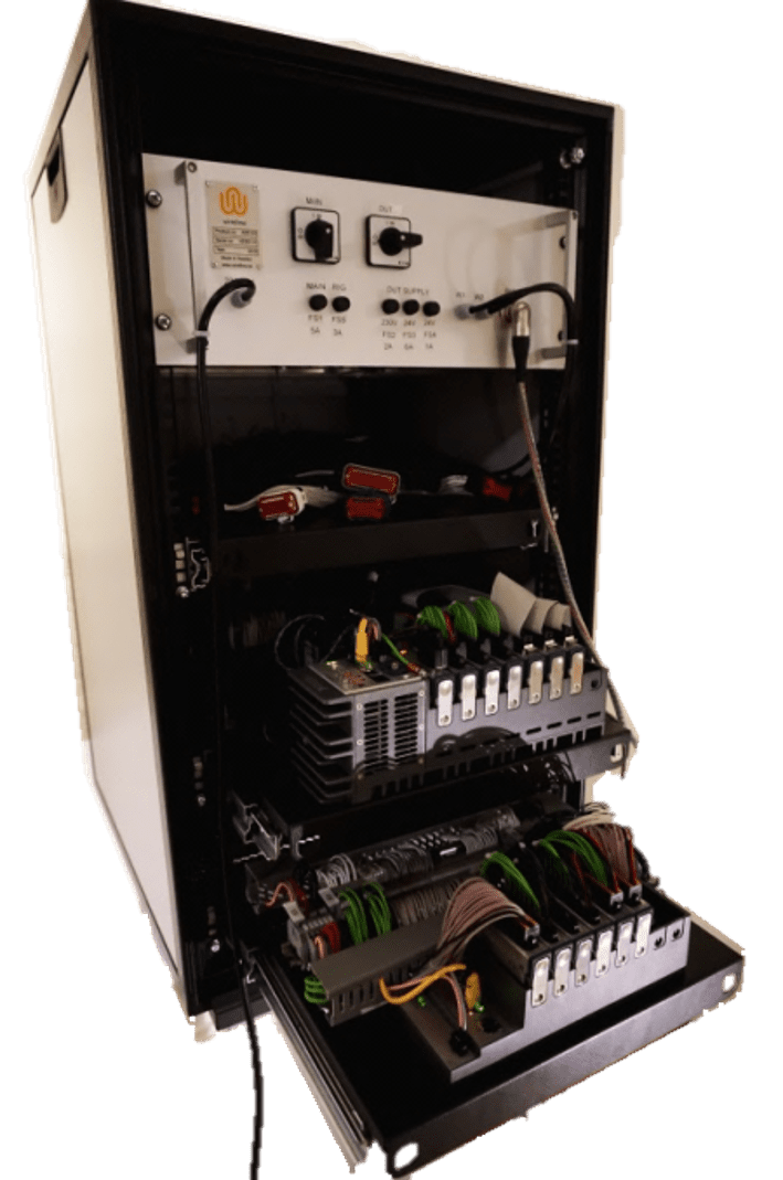
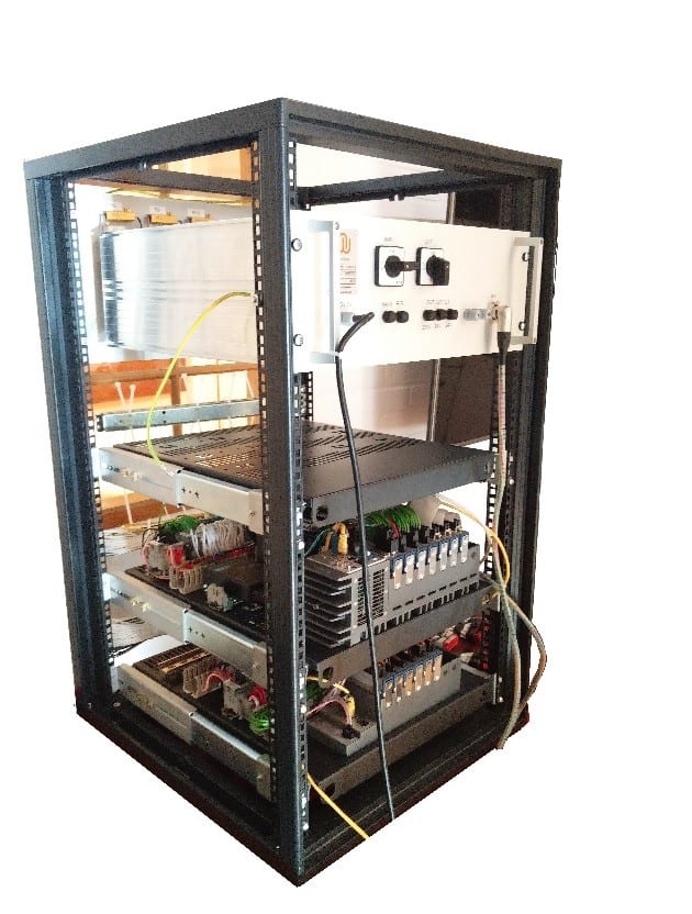
The system was built as a 19” half-height cabinet with the high voltage parts placed in a closed box. The I/O was placed on retractable shelves for easy access in case the prototype requirements changed in the future. One shelf in the cabinet was dedicated to the DUT.
Hardware
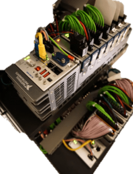
WireFlow designed the test system based on the modular CompactRIO platform from National Instruments™ (NI). It took one cRIO chassis plus one additional EtherCAT expansion chassis to be able to support the channel count in the system.
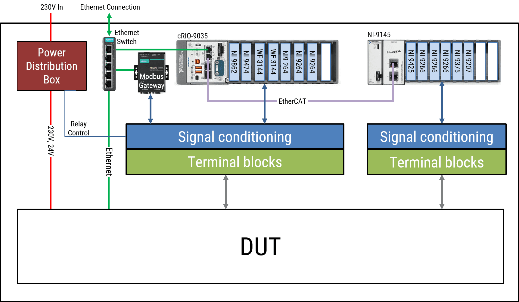
In order to support the amount of thermocouple (TC) channels, WireFlow developed a TC simulation board that is able to output the voltages corresponding to the Type-K and Type-R voltages (microvolt range). This TC board connects to a standard C Series AO module from NI, and combined with the scaling and calibration capabilities of the software it delivers TC voltages for the full temperature range, with a 0.5 degree resolution. A total of three TC boards were fitted in the system.
Simulating PT100 temperature sensors is different than TCs because of the way they work. PT100 sensors don’t have any thermal voltage, but instead returns a resistance corresponding to the temperature. The WireFlow WF3144 Programmable Resistor Module was created for exactly this type of resistive simulation, so no special electronics had to be developed. Scaling is done in the software to convert temperature to the expected PT100 resistance.
Both CompactRIO and EtherCAT have the ability to support both standard I/O modules through Scan Mode as well as custom I/O channels using LabVIEW FPGA. Since WF3144 is a third party module, and because the system is going to both generate and measure PWM signals, the FPGAs in both the CompactRIO and the EtherCAT chassis are programmed. The EtherCAT FPGA I/O is accessed through Scan Mode using User Defined Variables, and the FPGA I/O on the Compact RIO is accessed using the dynamic capabilities of the WireFlow measurement engine.
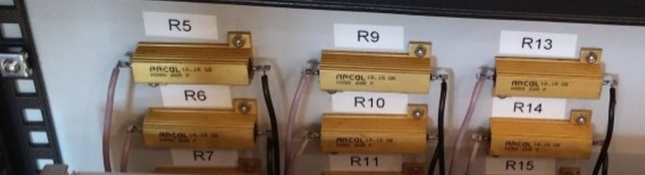
The real system consists of several external devices, and in order to make the DUT believe that the real system is actually connected; the test system also uses loads matching the real devices. These loads are placed inside the cabinet with enough ventilation to be able to dissipate all the heat generated in the load resistors.
A Power distribution box keeps the 230V separated from the other signals, and allows the customer to select 24V and/or 230V supply for the DUT, and this is even remote controlled.
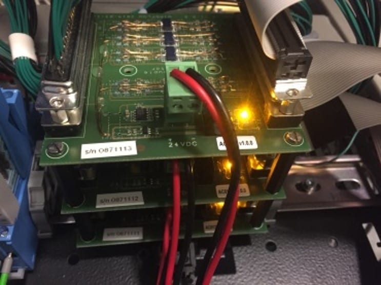
TC simulation board that is able to output the voltages corresponding to the Type-K and Type-R voltages (microvolt range)
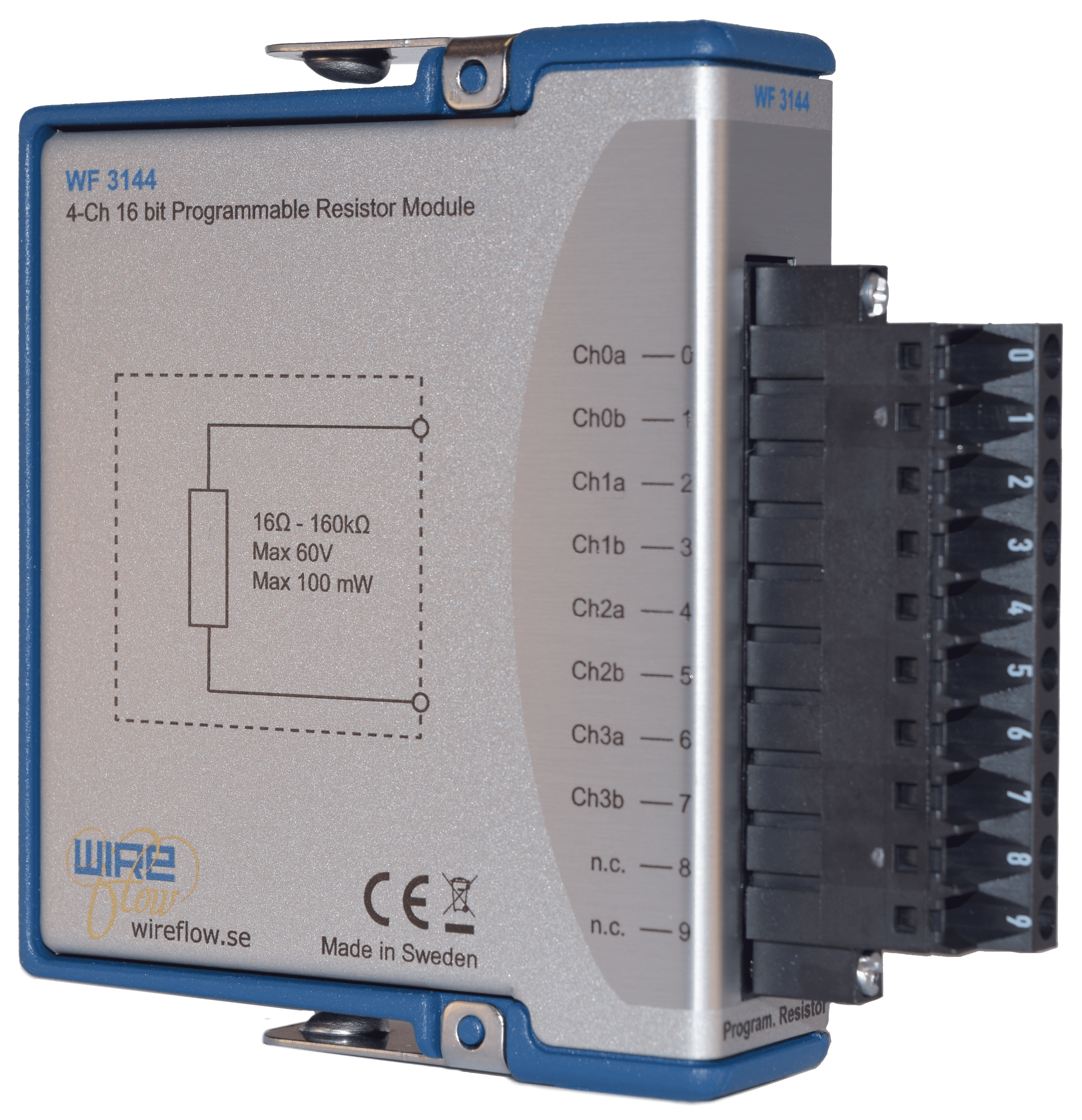
The WireFlow WF3144 Programmable Resistor Module
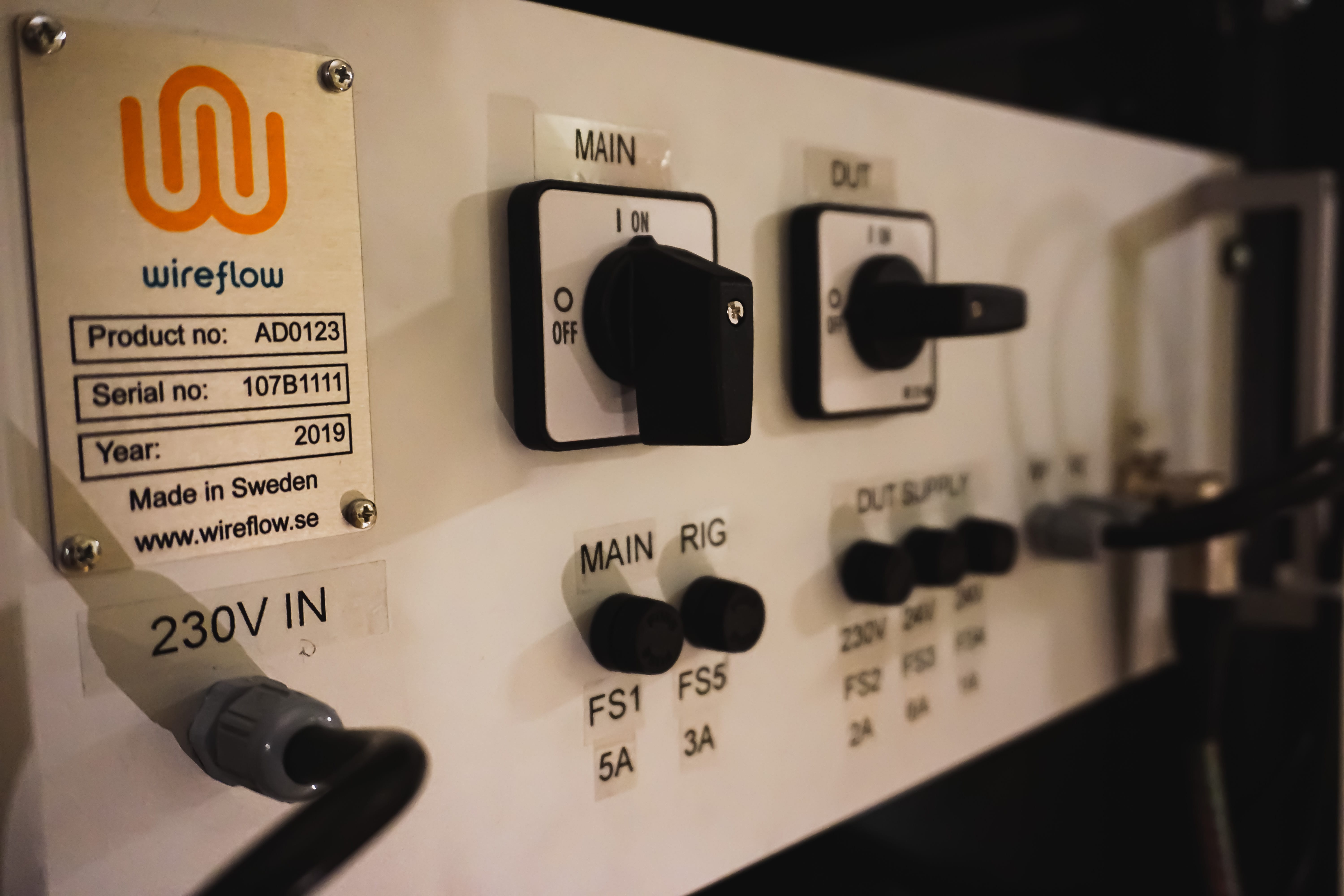
Power distribution box
Software
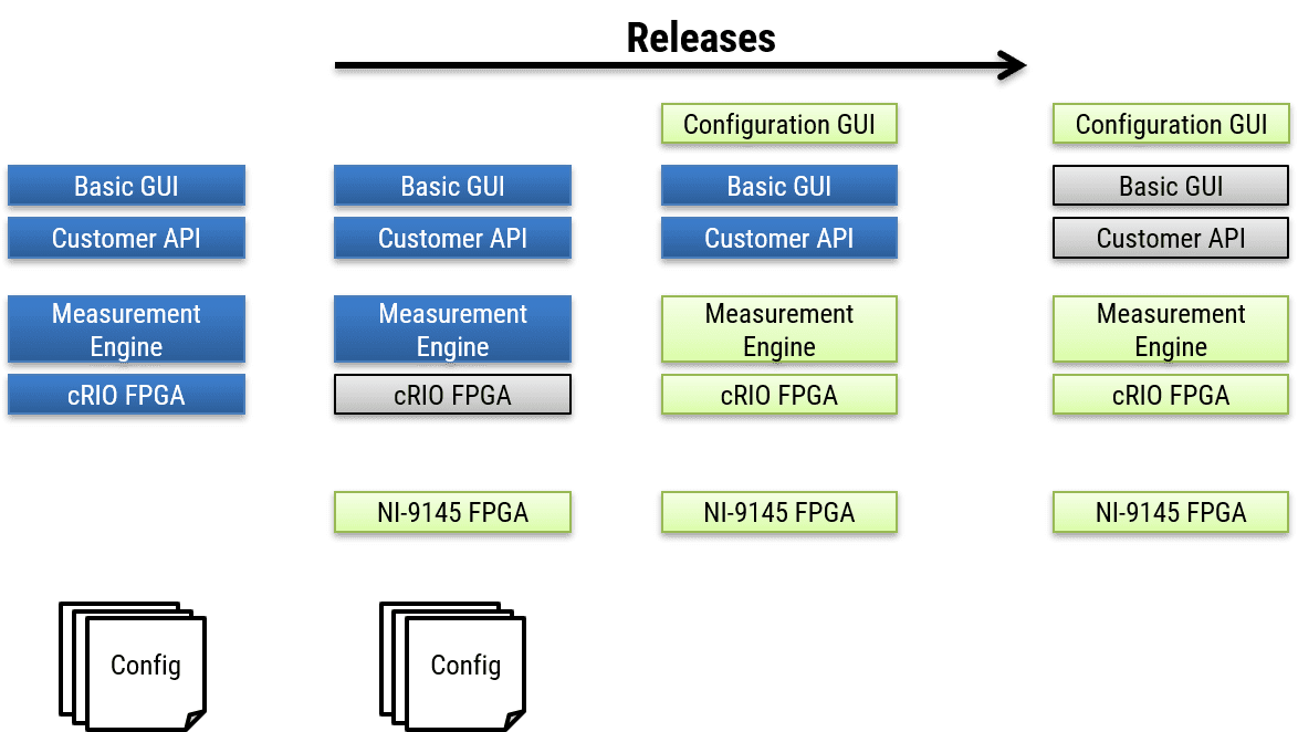
To make the system available to Azelio as soon as possible, WireFlow planned the software to be released in several steps.
The first step updated the old system to support most new I/O by updating the FPGA and adding an EtherCAT FPGA.
Second step. In the second step, the heart of the system was updated to support dynamic configuration, simulation models, CAN and additional Modbus interfaces (using the WireFlow engine), while still keeping the same Customer API.
Finally, the Customer API and the Basic GUI had minor updates to simplify interaction with the prototype.
Each release was carefully planned to add new functionality for Azelio, without breaking the backward compatibility.
The software is built in LabVIEW/LabVIEW FPGA, and consists of a Real-time engine, a configuration application and a TCP/IP communication protocol that allows access from the Azelio test scripts in Python.
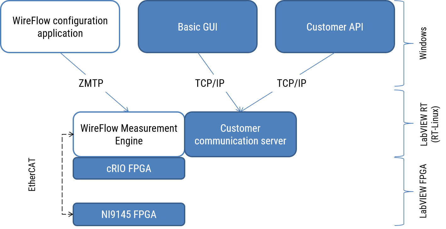
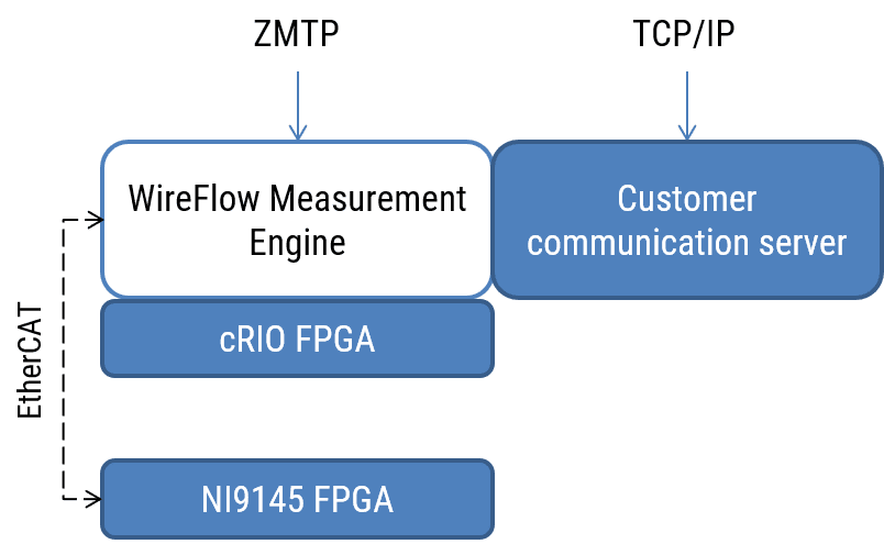
Real-time engine
The WireFlow Measurement Engine is highly dynamic in that it allows for dynamic reconfiguration of FPGA I/O and Scan Engine I/O. It also adds a layer of mapping functionality to allow scaling as well as calibration to the channels. The engine uses ZMTP (Zero MQ Transport Protocol) for communication. One reason for this is that it allows for concurrent connections out of the box and with a Command/Client built on top, this means that debugging of communication is built right into the engine. The customer wanted to re-use a proprietary network protocol in their python scripts, so the protocol was included as an add-on to the standard engine. This network protocol is using standard TCP/IP with the additional tweak of disabling the Nagle algorithm for increased performance when sending small packages.
Configuration GUI
The configuration of the engine is done with the accompanying Configuration GUI.
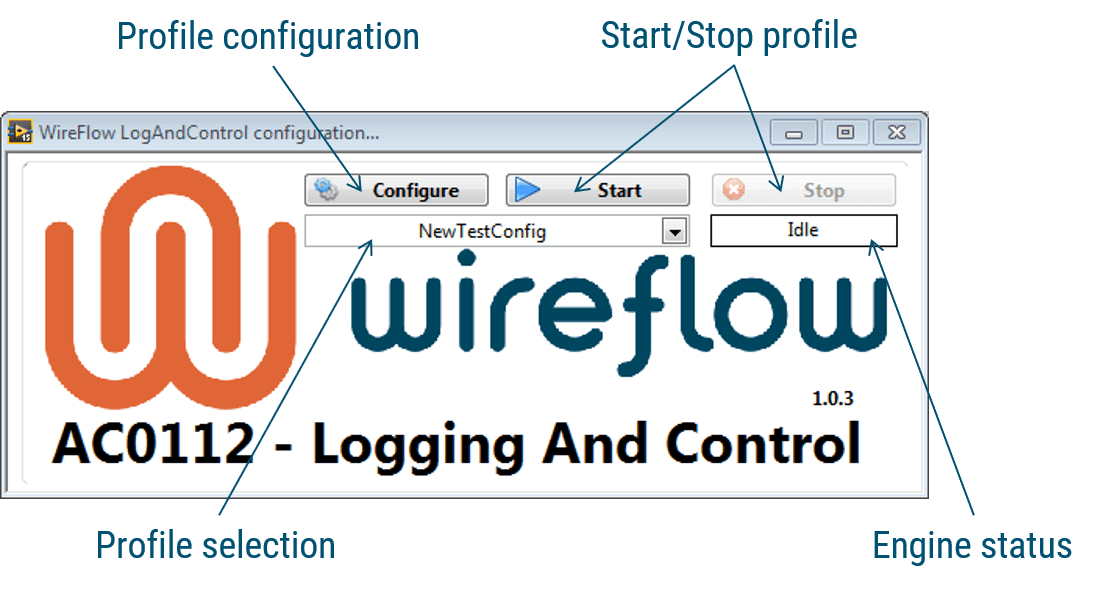
From the Main Panel it is easy to switch between configurations depending on what is being tested. In the Configuration Panel, the customer can make changes to the system, like adding bitfiles, changing mapping and scaling between channels.
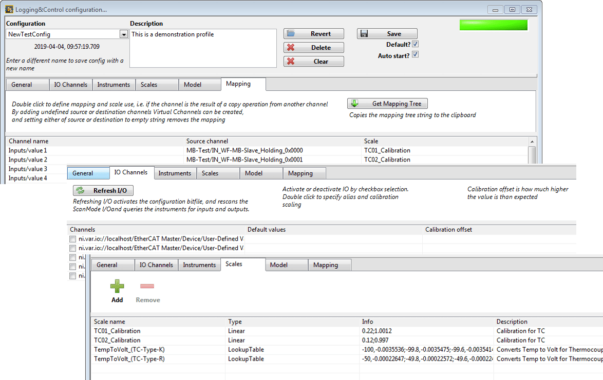
In addition, it is possible to add models that run in-line with all I/O. The system uses “Model Interface Toolkit” (MIT) for LabVIEW, so the models must follow the MIT guidelines to be supported. Once the model has been added it can be configured, i.e. the configuration parameters of the models can be specified.
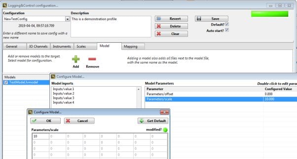
The system also supports custom FPGA bitfiles, and can access the I/O of the FPGA in two ways, either by Scan Mode (and UserDefinedParameters) or by dynamically accessing the FPGA front panel items directly.
Since the configuration supports many saved configurations (saved on the CompactRIO), it supports configurations for different users and different prototype versions. The system has a default configuration that is set to start when the CompactRIO starts, making it easy to get up and running using the TCP/IP API directly, i.e. no configuration is necessary at the time of testing.
Summary
One requirement of the system was to be able to support testing of the current version of the ECU prototype. Another requirement was to make it easy to upgrade the system to support testing of future versions of the prototype, which may include changed or increased I/O. Since the hardware and software was built with expansion in mind, many changes and additions can be made without having to change any LabVIEW code:
- The system has a number of spare I/O channels, and these are already available in the SW
(without mapping or scaling) - The customer can add new I/O modules in free slots on the chassis, and the software
will automatically detect and start using these I/O channels. - Changes that only require change of mapping/scaling (e.g. change of Thermocouple type),
can be done in software. - The TCP/IP API can be used from any language, and supports all I/O in the system.