Developing a Control and Monitoring System for a Vertical and Floating WindTurbine for Deep Sea Deployment
The Challange
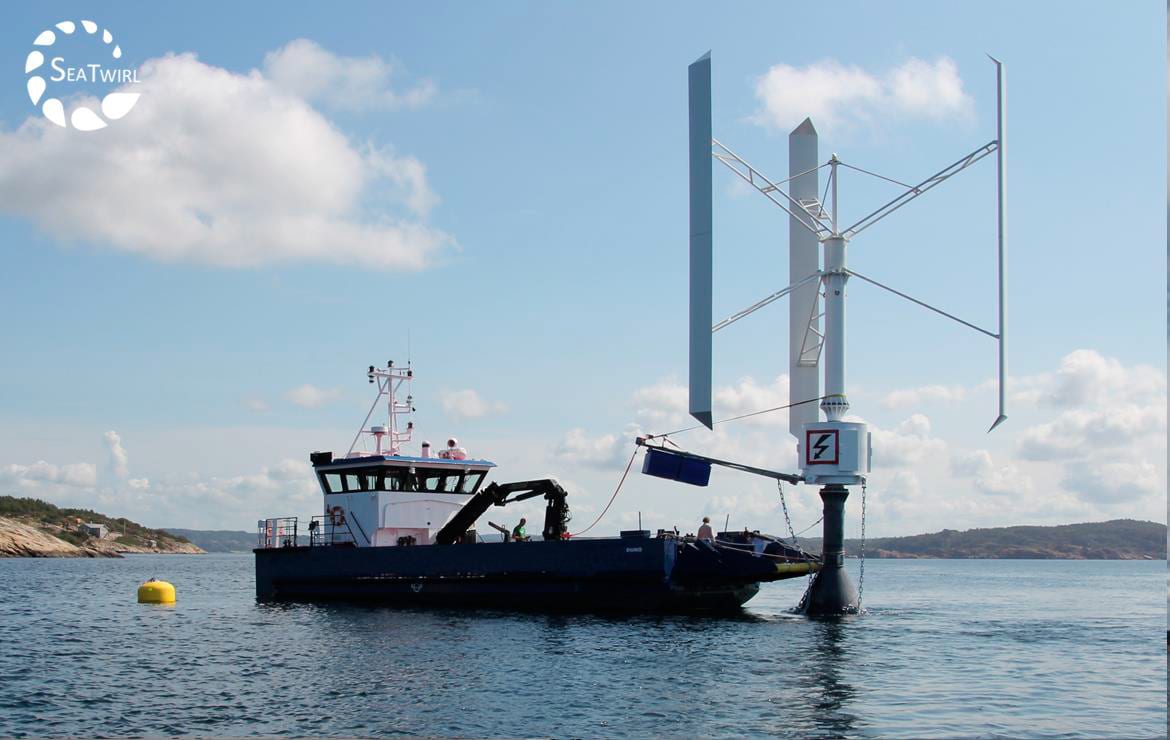
SeaTwirl designs floating wind turbines built for deep sea deployment. The ambition is to provide the most cost effective product for the production of renewable energy. By evaluating a 30 kW grid-connected floating wind turbine prototype in Lysekil Sweden, knowledge will be generated which will become necessary for future products that will be in the 10 MW class. For this SeaTwirl needs a powerful control and measurement system that can control the wind turbine and also record measurement data that can be used to analyze the functionality and performance of the wind turbine.
– Gabriel Strängberg, Managing Director at SeaTwirl AB
The Solution
To take on the challenge to design a powerful control and measurement system for the wind turbine, SeaTwirl teamed with the National Instruments Alliance partner WireFlow. The control system was built around a National Instruments Compact RIO that executes a real-time LabVIEW control- and measurement application. WireQueue, the secure IoT solution for LabVIEW from WireFlow, enables SeaTwirl to do remote monitoring of the floating wind turbine over the 3G network.
Innovative design
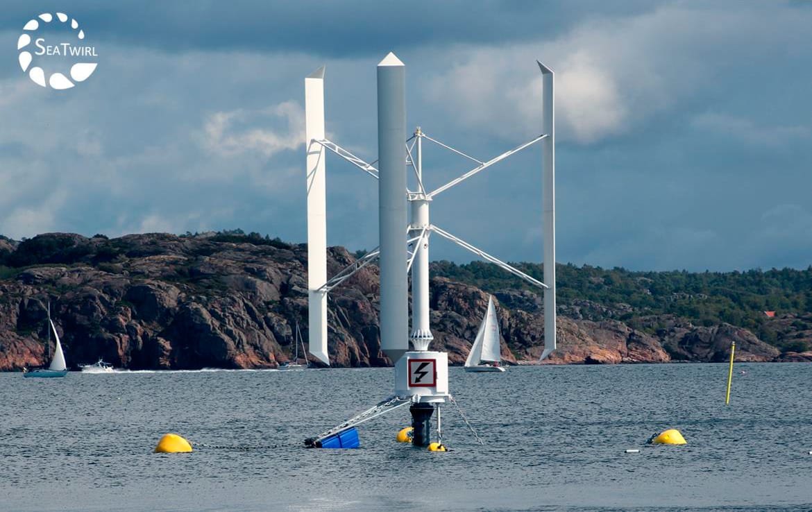
SeaTwirl designs floating wind turbines built for the ocean. These wind turbines are easier to build, install and they require less maintenance than traditional offshore wind turbines. The ambition is to provide the most cost-effective solution for production of renewable energy
The SeaTwirl wind turbine has a simple robust design, few moving parts and can be placed in deep waters where wind conditions are good. (It is one of few power plants possible to deploy in the ocean.)
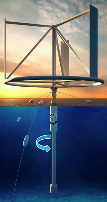
The underwater structure contains a buoyancy part and at its lowest point, a weight part. This makes the structure stable. The full body from the wind turbine in the top to the lowest underwater weight part is rotating as one piece and all its weight is carried up by the water.
To translate the kinetic energy into electrical energy a generator is placed around the rotating tower. The generator is placed above the sea level and is held in place using anchoring to the bottom of the sea. Since Sea Twirl is using an anchoring method, it can be placed in deep waters.
The offshore winds are stronger, blows more hours and are more uniform than coastal winds. A floating wind turbine can be placed in new areas in the ocean, where wind turbines previously could not be deployed because of the depth of the water.
It has a vertical axis wind turbine
A vertical wind turbine can absorb wind energy independent on wind direction. There is no need for any yaw or pitch mechanism to face the blades to or from the wind. Fewer moving parts imply lower maintenance costs and less downtime.
Vertical wind turbines also have a higher structural limit and can be built larger than horizontal axis wind turbines, reaching a higher level of cost-effectiveness.
The SeaTwirl wind turbine requires a robust and powerful control system. It shall continuously measure the wind and control the rotational speed according to an algorithm making the power generation efficiency optimal. The control system must also perform status monitoring, and in case of any abnormalities stop the rotation and take the system into a failsafe mode.
Since the high power frequency inverter is located on-shore the control system must be distributed. It must be able to interact with sensors and machinery located both on-shore and off-shore.
SeaTwirl personnel need to be able to monitor the operations from the SeaTwirl control room located in Gothenburg, so a secure remote monitoring link is required. To complicate matters further, the wind turbine is located in a remote bay outside Lysekil on the west coast of Sweden. No fixed internet services are available at the location.
WireFlow
To take on the challenge to design a powerful control and measurement system for the wind turbine, SeaTwirl teamed with the National Instruments Alliance partner WireFlow. WireFlow main office is also located in Gothenburg, Sweden. WireFlow provides products and services for the National Instruments hardware and software platforms. WireFlow’s expertise in designing customized distributed control systems was the main factor for SeaTwirl to team with WireFlow. WireQueue, a Secured IoT Toolkit from WireFlow, would prove to be a real hit when remote monitoring was to be implemented.
The control and measurement system
Required functions of the control system
The main task for the control system is to continuously measure the wind and control the rotational speed to keep power generation efficiency at its optimum. The rotational speed of the wind turbine depends on how much the wind blows in conjunction with how much power is produced in the three electric generators that are located in the wind turbine. When starting up the rotation of the turbine, the frequency inverter controls the three electric generators that now act as motors to rotate the turbine up to a specific speed. When the wind pushes the turbine blades the generators will break the rotation to the speed set by the frequency inverter. This will make the motors act as generators and energy will flow from the wind turbine to the frequency inverter and in to the power grid.
The control system must also do status monitoring, and in case of any abnormalities stop the rotational speed and take the system into a failsafe mode. The control system will monitor various status parameters such as:
- The status of the frequency inverter and the generators
- Status of the mechanical breaks
- Temperature, wind speed and other environmental parameters
- Mechanical forces that by measuring vibrations, inclination and torque
Measurement data shall continuously be logged onto a large disc so that SeaTwirl engineers can use this data for analysis that will give knowledge on how the wind turbine behaves in its real environment.
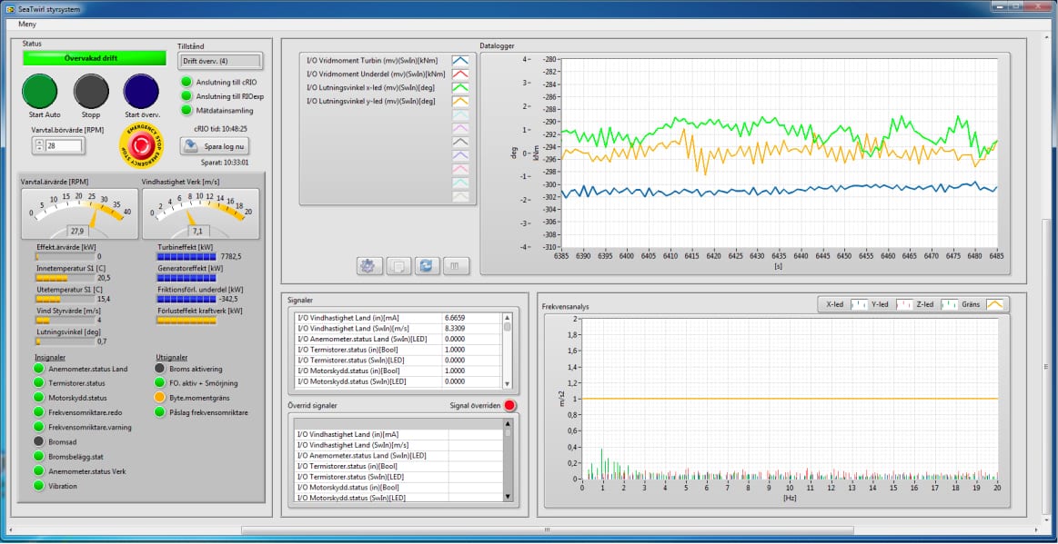
It shall be possible to connect to the control system with a pc running a program that acts as a operator panel. This operator panel shall display system status and it shall be possible to control the turbine manually. The operator panel shall also provide a graph that shows vibrations and movements in the x, y and z axis. A chart shall be available where the operator can select which of the measured signals he wants to be displayed.
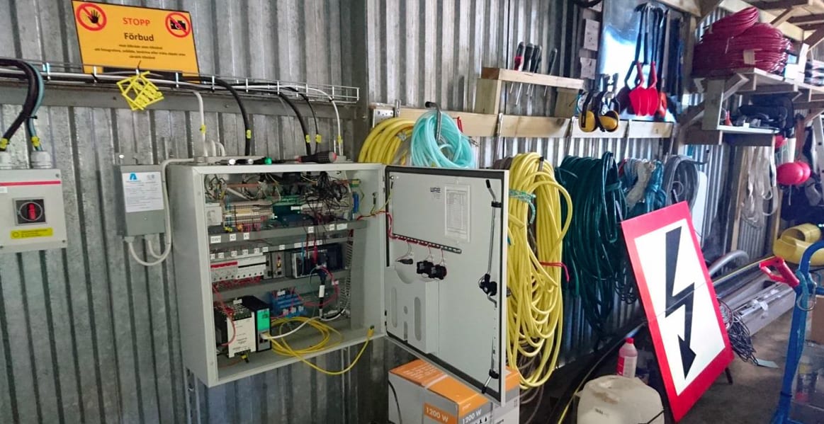
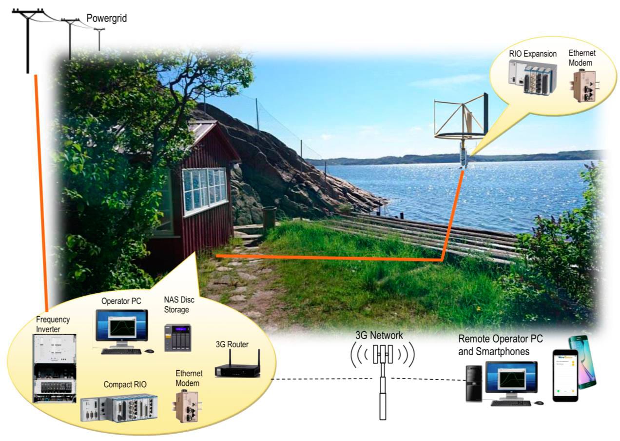
The heart of the control system is a National Instruments CompactRIO that executes a real-time control application developed in LabVIEW. The CompactRIO is installed in the on-shore equipment building next to the frequency inverter. The CompactRIO is equipped with 4-20mA analog I/O modules and 0-24V digital I/O modules. These modules controls the frequency inverter and the mechanical breaks located in the wind turbine. The modules also measures wind, temperature other types of environmental parameters. The CompactRIO is attached to a local area network, LAN, together with the other parts of the control system:
- An Ethernet RIO expansion chassis, executing a LabVIEW FPGA program that records data at high speed from accelerometers, strain gauges etc located off-shore in the wind turbine
- A network attached storage, NAS, in which large amounts of measurement data is stored
- A 3G router that makes it possible to do remote monitoring of the control system, since no fixed internet connection exists at the site
- An Operator PC that can be connected enabling manual control and monitoring of the system
The Ethernet connection out to the wind turbine is made through the sea cable. Ethernet modems are used to create a stable Ethernet connection between the CompactRIO and the RIO expansion unit.
The control system functionality
The CompactRIO executes a high priority, predictable real-time control loop. During every loop the following actions are performed:
-
Check if there is any command from the PC operator panel that shall be handled
-
Read data from the I/O modules in the CompactRIO
-
Collect high speed sensor data received from the RIO expansion chassis in the turbine
-
Do a moving average on applicable raw sensor signals
-
Scale physical input signals from electrical to real units, e.g. from mA to degC
-
Execute signal processing algorithms like calculating generator power [W] based on rotation speed [RPM] and torque [kNm]
-
Execute the system control state machine having states such as: initiation, speed-up, running, breaking, emergency stop etc.
-
Do a FFT analyze to find vibration tones based on accelerometer signals
-
Scale output signals from physical to electrical units, e.g. from RPM to mA.
-
Write output signals to the CompactRIO modules
-
Stream data to low priority loops in the CompactRIO application that handle various tasks with lower priority than the main control loop
In parallel with the high priority loop described above, the CompactRIO also executes a few loops with lower priority that executes tasks such as:
-
Collect measurement data and append it to log files on the local CompactRIO disc every 10 seconds. Use FTP to move these files from the CompactRIO to the NAS every 60 minutes
-
If a PC operator panel is connected; stream data to the PC
-
Send a status report to the WireQueue IoT server once a minute
-
Monitor connection status to the other parts of the control system; PC, NAS, WireQueue and RIO expansion unit. In case of any lost connection start re-connection attempts
Conclusion
The CompactRIO was the natural choice for this application since it provides the possibility to quickly design a deterministic and robust control system using of-the-shelf hardware. The ability to put some of the I/O modules in a RIO expansion chassis inside the turbine, and to connect it using the sea cable, formed a very convenient solution. The end result is a rugged, high performance, distributed I/O control system.
Using LabVIEW we could, in a short development cycle, design and implement a networked system that shares the collected data between the CompactRIO and the other parts of the control system; the NAS, the RIO expansion unit, the PC operator panel and the smart phones connected to the WireQueue IoT server.
