Vinga Cycle Rig System
A Battery Testing Solution for Brompton Bicycle
The Challenge
Brompton Bicycle builds one of the most iconic foldable commuter bikes and is Britain’s largest bike producer.
Upon introduction of their first electric bike to the market, they needed a top-of-the line battery testing solution. Initially, the requirement was to test three packs, but the solution had to be scalable for easy upgrade to up to ten packs.
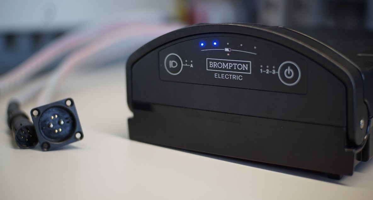
Figure 1 – Brompton Electric battery pack

Figure 2 – Brompton Bicycle
The Solution
WireFlow has extensive experience both with automated testing equipment and li-ion batteries. We designed a flexible and compact test solution that could scale up according to Brompton’s future needs.
The core of the WireFlow solution is the Valand battery test and measurement software, running on a cRIO industrial controller which controls bi-directional PSUs (Power Supply Units) for charge and discharge.
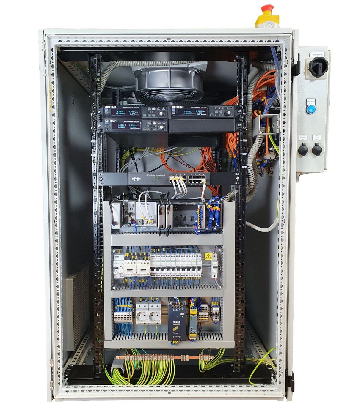
Figure 3 – Vinga System in Cabinet
Energy efficient hardware with Real-time control
The system is controlled by a cRIO-9057 industrial controller that executes test sequences for each battery pack independently. A remote PC is used for management and configuration of the system.
Each battery pack has a set of dedicated hardware (CAN-bus, PSU and contactors).
The CAN-bus is used for interfacing with the battery pack Battery Management System (BMS). State variables and error messages can be read, logged, and acted upon via this interface. It is also possible to send commands to the battery pack.
The network-controlled PSUs are regenerative and used for charge and discharge. By using regenerative PSUs, the power from discharge is fed back to the grid, minimizing heat dissipation thus allowing a more compact size, as well as lowering the operating cost. Ten packs can be tested with a cabinet only 1200mm (24HE) high.
As with many bicycle battery packs, the charge and discharge connectors are separate. To fully automate the testing and to control the current path, the system has a set of contactors that can switch between connectors when needed.
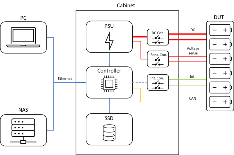
Figure 4 – Hardware Architecture (showing single battery pack)
Cables between cabinet and DUT (Device Under Test) are terminated in a side-mounted connection box with terminal blocks. With this solution, it’s possible to vary the cabling for each pack individually so that multiple battery types can be tested concurrently.
A common emergency switch button is mounted on the cabinet if there is a need to quickly terminate testing.
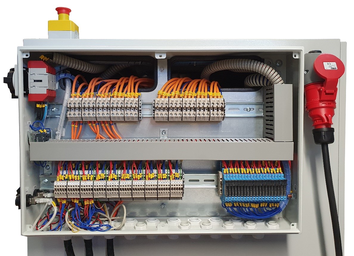
Figure 5 – IO-box for connecting the battery pack
Valand Software – Flexible with Scripting
The Valand software is based on WireFlow’s Valand framework. The Valand
framework has been developed specifically for battery cell and battery pack testing.
Valand software is purpose-built for running test sequences for battery cells and
packs. A test sequence is made up of test script building blocks, which during
execution write variable values and test results to log files.
It is also possible to control the system manually without using sequences or
scripts. This can be useful both during script development and for simple testing.
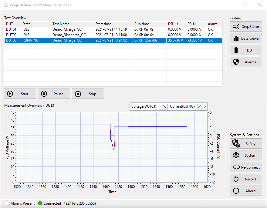
Figure 6 – Main Window on PC
The test scripts are written in a C-style language where the test engineer can
implement almost any type of test that the hardware supports. The built-in editor
can validate the script for syntax errors and has a help module describing each
function.
All battery pack variables are available in the scripting environment, so it is easy to
set up tests with almost any criterion. Tests can range from simple test cases such
as cycling between pre-defined SOCs or voltage levels whilst doing coulomb
counting; to more advanced test cases such as triggering error conditions for
validation of BMS software logic.
Scripts and sequences are stored in a library for easy re-use.
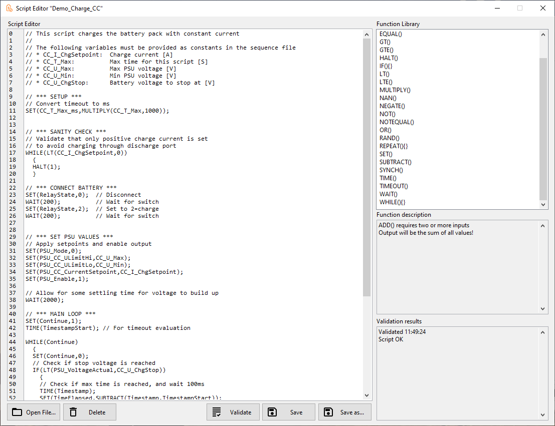
Figure 7 – Test Script Editor on PC
The system includes an independent alarm function that runs in the background,
which monitors variables selected by the user and compares them with userdefined limits. If a value is outside the limits, the system is put in a safe state (PSU
disabled and contactors disengaged). Thus, if a test sequence is running, it will be
halted. Alarm limits can be set individually per battery pack and the failure of any
one pack won’t affect the others.
The alarm function can also be used to configure OVP (Over Voltage Protection),
UVP (Under Voltage Protection), OCP (Over Current Protection) and UCP (Under
Current Protection) for each battery pack.
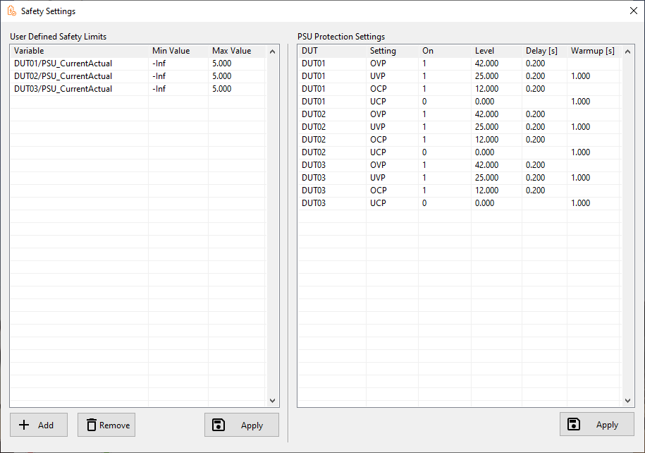
Figure 8 – Alarm Settings
