Extending the capability of VeriStand with a “Custom Device”
To integrate a remote UDP-device as a node in VeriStands system explorer
The Challenge
A WireFlow customer working in the automotive segment has
They asked for a software module that could act as a gateway between the local VeriStand system and a device on the network, passing signal values between them in UDP-packets. We call the module a “UDP Gateway”.
The Gateway-module should Integrate fully in the “System Explorer” i.e. VeriStands native graphical configuration interface the way other nodes
The signals to transmit and receive should be configurable. The number of signals, their naming, the order of the signals in the packets and the byte order must all be easy to setup in the configuration panel.
It should also be possible to enable and disable the transmission of UDP-packets from the gateway.
The Solution
It was decided that WireFlow would develop a “Custom Device” for our customer.
A “Custom Device” is a plugin module for VeriStand, implemented in LabVIEW using a framework defined by National Instruments. The plugin presents itself as a node in VeriStands system explorer, just as any other types of VeriStand-nodes, with Input/Output terminals and a configuration page.
This was what the customer needed, and since WireFlow has done similar things earlier, and is familiar with both LabVIEW and VeriStand, we could deliver a working solution in good time for their needs.
In Figure 1 below you can see how the custom device integrates into the system explorer.
On the left-hand side of Figure 1, surrounded by a yellow border, you can see two nodes named “UDP-Gateway: My 1st remote device” and “UDP-Gateway: My 2nd remote device”. One is unfolded to show all input and output signals. Each of the nodes is configured in a configuration page to the right. There you can configure:
- The name of the remote device.
- Communication settings.
- The signal configuration of the incoming and outgoing UDP-packets.
Summary
A custom device is a powerful way to extend the functionality of a VeriStand-based system. This document shows just one example of how the reach of a system can be widened and how it can be set up for new tasks. The possibilities though are almost unlimited, since the custom device is developed in LabVIEW which gives access to a generic development tool with optimized performance and compatibility with regards to your platform.
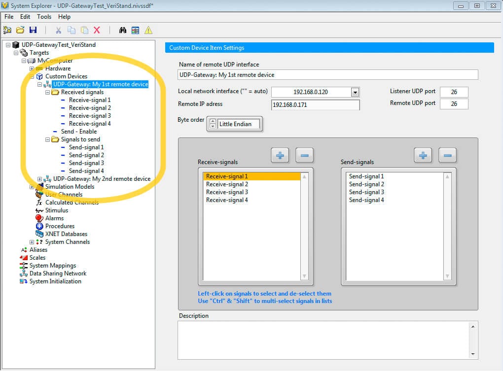
Figure 1. The custom device in use in a VeriStand project